What Is a Solenoid Pump and How Does It Work?

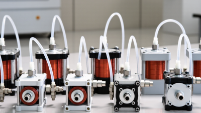
A solenoid pump is a compact device that moves liquid through controlled electromagnetic action. It appears in coffee machines, medical equipment, vehicle systems, and industrial dosing units. Despite its small size, its timing and pressure control can strongly affect system performance.

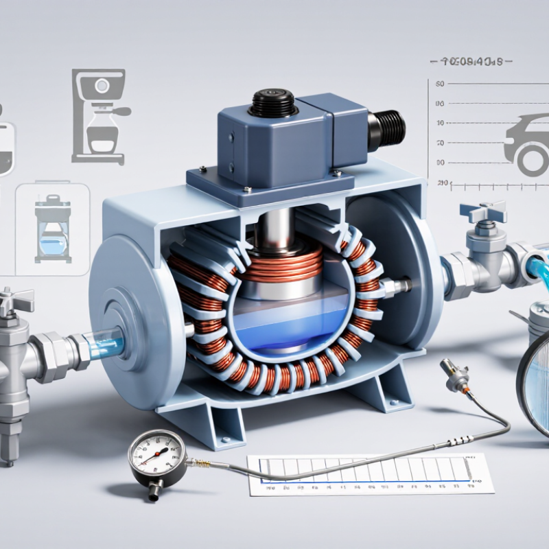
Inside the pump, an electrical coil creates a magnetic field when current flows. This field pulls a movable plunger or diaphragm. That movement changes the chamber volume and opens or closes internal check valves. Liquid enters through the inlet, then leaves through the outlet during the return stroke. The process repeats rapidly. Simple, but not effortless.

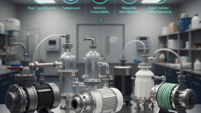
Flow depends on voltage, liquid viscosity, pressure, temperature, and stroke frequency. A pump rated for water may behave differently with oil or cleaning chemicals. Engineers should check the manufacturer’s flow curve, pressure range, wetted materials, and duty cycle before installation. A practical inspection may reveal air bubbles, unusual clicking, overheating, or a restricted filter. These clues matter.

Not every solenoid pump delivers perfectly smooth flow. Pulsation can remain visible in a transparent tube. That is normal in some designs, though it may require a dampener. Misreading the pressure rating is a common mistake. So is ignoring heat buildup during continuous operation. Reliable selection combines datasheet evidence with real operating conditions, not appearance alone. This guide explains the pump’s main parts, operating sequence, advantages, limitations, and maintenance considerations. It also examines where simplified explanations fail, because real systems rarely behave exactly like diagrams.
What Is a Solenoid Pump and How Does It Work?

What Is a Solenoid Pump?

A solenoid pump is a compact metering pump driven by electromagnetic force. When its coil receives an electrical pulse, the magnetic field moves a plunger or flexible diaphragm. This movement creates pressure, opening one check valve and closing another. Liquid then travels through the pump chamber in measured strokes. Unlike a centrifugal pump, it does not need a continuously spinning impeller. It is commonly used for water treatment, laboratory dosing, cooling systems, and low-flow chemical delivery.

Its accuracy depends on stroke length, pulse frequency, liquid viscosity, and back pressure. The U.S. Department of Energy reports that pumping systems can represent 25% to 50% of electricity use in some industrial facilities. Efficient control therefore matters, even for small pumps. The WHO and UNICEF Joint Monitoring Programme reported that 2.2 billion people lacked safely managed drinking water in 2022. Reliable dosing equipment can support treatment processes, but it cannot replace proper system design. That distinction is often missed.

Tips: Check valve compatibility before installation. Keep the suction line short and firmly supported. Add a calibration column for real flow testing. A displayed setting is not proof of actual output. Temperature, trapped air, and worn diaphragms can change performance. I have found that simple field checks reveal more than a perfect specification sheet. Even then, results may vary. Record flow readings under working pressure, not only during bench testing.

Key Components and Their Functions

What Is a Solenoid Pump and How Does It Work?

Key Components and Their Functions

A solenoid pump converts electrical pulses into controlled fluid movement. Its coil creates a magnetic field when energized. The field pulls a movable iron plunger, or armature, through the pump head. A spring returns it when power stops. This repeated stroke creates suction and discharge.

Small mechanism. Precise timing.

The coil is the actuator, but it is not the whole pump. The plunger supplies mechanical force, while the diaphragm or piston transfers that force to the liquid. In chemical-duty designs, a diaphragm can isolate fluid from the coil and moving metal. Inlet and outlet check valves control one-way flow. They must seal against actual pressure, temperature, and viscosity. The housing supports alignment and contains leakage. A controller adjusts pulse frequency, stroke length, or both.

Field testing often reveals overlooked problems: trapped air, softened valve seats, and clogged strainers. These faults can reduce dosing accuracy before the coil fails. The U.S. Department of Energy reports that pumping systems may consume 25% to 50% of industrial facility electricity (Pumping Systems Tip Sheet, 2004). Its Improving Pumping System Performance sourcebook also identifies potential savings of 20% to 50% in many systems. A solenoid pump is modest in power, yet frequent cycling still creates heat. Published flow ratings often use clean water. Real liquids behave differently. That is where a neat specification can become misleading.

How a Solenoid Pump Moves Fluid Step by Step

What Is a Solenoid Pump and How Does It Work?

A solenoid pump uses an electromagnetic coil to move a small piston or diaphragm. The process begins when electrical current enters the coil. The coil creates a magnetic field and pulls a metal plunger inward. This movement changes the pressure inside the pump chamber. Fluid then enters through an inlet valve.

When the current stops, a spring pushes the plunger back. The chamber pressure rises during this return stroke. The inlet valve closes, while the outlet valve opens. Fluid leaves through the discharge port. This cycle repeats rapidly, creating controlled pulses of liquid flow.

Small details affect real performance. A technician should check the voltage, fluid temperature, tubing size, and valve condition. Incorrect voltage can weaken the stroke or overheat the coil. Air bubbles may also reduce output and create uneven pulses. The pump may sound normal but deliver less fluid. That is easy to miss. In field testing, measuring actual flow is more reliable than trusting sound alone. Some systems need a filter before the inlet, especially when suspended particles could block the valves. Flow may also change as seals wear, so a pump that worked well last month deserves another inspection. The working principle is simple, but reliable operation depends on careful setup and regular observation.

What Is a Solenoid Pump and How Does It Work? - How a Solenoid Pump Moves Fluid Step by Step

Step / Dimension Main Component What Happens Fluid Movement Important Data or Condition
1. Electrical command Solenoid coil and control circuit A controller sends a voltage pulse or repeating electrical signal to the coil. No fluid movement occurs yet; the magnetic actuator is being energized. Common control supplies include low-voltage DC or mains-frequency AC, depending on the pump design.
2. Magnetic force develops Electromagnetic coil and iron armature Current through the coil creates a magnetic field that pulls or pushes the armature. The pump chamber begins a controlled compression or displacement stroke. The stroke frequency determines how many pumping cycles occur per unit of time.
3. Inlet valve closes Check valve on the suction side Pressure generated in the chamber seats the inlet check valve. Fluid is prevented from flowing backward toward the supply container. Valve sealing depends on fluid cleanliness, viscosity, temperature, and pressure difference.
4. Discharge valve opens Check valve on the outlet side The outlet valve opens when chamber pressure exceeds downstream pressure by the valve’s opening requirement. Fluid is pushed into the discharge line. A check valve allows one-way flow and helps isolate the pump from back pressure.
5. Diaphragm or plunger displaces fluid Flexible diaphragm or reciprocating plunger The actuator changes the volume of the sealed pumping chamber. A measured pulse of fluid leaves the chamber. Diaphragm designs keep the actuator separated from the pumped liquid, which is useful for corrosive or contaminated fluids.
6. Coil de-energizes Return spring and armature When the electrical signal stops, the magnetic field collapses and the spring returns the actuator. The chamber expands and creates a partial vacuum. The return stroke must be fast enough to refill the chamber before the next pulse.
7. Inlet valve opens Suction-side check valve Lower pressure in the chamber allows the inlet valve to open. Fresh fluid enters from the reservoir or suction pipe. Adequate suction head and properly sized tubing reduce the risk of cavitation and incomplete filling.
8. Cycle repeats Controller, coil, actuator, valves, and chamber Repeated electrical pulses produce repeated suction and discharge strokes. The pump delivers a pulsing flow that can be regulated by pulse frequency, stroke length, or duty cycle. Average flow is approximately proportional to displacement per stroke multiplied by strokes per unit of time, subject to slip and operating losses.
Typical operating range Small electrically actuated metering pumps Designed for compact, intermittent, or accurately metered liquid delivery. Flow is commonly delivered in discrete pulses rather than as a perfectly continuous stream. Representative flow capacity may range from a few millilitres per minute to several litres per minute; pressure capability varies widely by construction.
Key advantages and limits Complete pump assembly Provides compact size, simple electronic control, and repeatable dosing without a continuously rotating motor. Best suited to clean liquids and applications where pulsed delivery is acceptable or can be damped. Performance can decrease with excessive viscosity, entrained air, blocked valves, high back pressure, or incompatible wetted materials.

Note: Operating values are representative ranges for small solenoid-driven diaphragm or plunger pumps. Actual flow, pressure, stroke volume, temperature range, and chemical compatibility depend on the specific pump construction and application.

Common Types and Operating Configurations

What Is a Solenoid Pump and How Does It Work?

A solenoid pump uses an electromagnetic coil to create mechanical movement. When current reaches the coil, it pulls a metal plunger or armature. A spring or opposing magnetic field returns it when power stops. That repeated movement draws liquid through an inlet and forces it through an outlet. Short pulses matter.

Common designs include direct-acting plunger pumps, diaphragm pumps, and bellows pumps. A plunger pump suits clean liquids and steady pressure. A diaphragm pump isolates the liquid from the coil, making it useful for corrosive or contaminated fluids. Bellows designs handle delicate liquids, although their flexible parts may fatigue over time. The choice is not cosmetic. Liquid viscosity, particle content, temperature, and required pressure all influence performance.

Operating configurations vary by application. Intermittent dosing uses timed pulses, while continuous operation uses a controlled duty cycle. Some pumps use normally closed inlet and outlet valves; others use normally open paths for rapid release. Single-head layouts provide simple dosing, while dual-head arrangements can balance intake and discharge. Stroke length, pulse frequency, and valve timing also affect flow accuracy. In field testing, the displayed flow rate rarely matches reality perfectly. Air bubbles, warm liquid, and worn valves can change the result. A common design mistake is sizing the pump only by maximum flow. Pressure at the discharge point deserves equal attention. Check actual output with the intended liquid, not water alone.

What Is a Solenoid Pump and How Does It Work?

A solenoid pump uses an electromagnetic coil to move a plunger, diaphragm, or bellows. Each energized and de-energized cycle creates suction and discharge through check valves. The chart shows representative upper-end operating frequencies for common pump constructions.

Diaphragm and piston designs are widely used for metering because their reciprocating motion produces a controlled pulsed flow. Bellows pumps are commonly selected for gentle, low-flow transfer, while direct-acting plunger pumps can operate at higher cycle rates when compact intermittent delivery is required. Actual performance depends on pressure, fluid viscosity, stroke length, temperature, and valve design.

Values shown are representative engineering figures in strokes per minute, not manufacturer-specific ratings.

Applications, Benefits, and Limitations

A solenoid pump uses an electromagnetic coil to move a small diaphragm or piston. When electricity reaches the coil, magnetic force creates a controlled pumping stroke. When power stops, a spring returns the mechanism. This repeated motion moves liquid through inlet and outlet check valves. Flow is usually pulsed, not perfectly continuous. That detail matters.

Solenoid pumps suit laboratory dosing, water treatment, medical equipment, fuel systems, and compact cooling circuits. They offer accurate metering, fast switching, and simple electronic control. Their small size helps engineers install them near sensors or narrow tubing.

The U.S. Department of Energy’s Improving Pumping System Performance guide identifies pumping systems as responsible for roughly 25% of industrial motor energy use. A properly sized metering pump can reduce unnecessary circulation and control chemical use. It can also prevent costly overfeeding.

Limitations become clear under heavy duty. Solenoid pumps often deliver low flow rates and modest pressure. Their diaphragm and valves can wear when liquids contain particles. Pulsation may disturb sensitive processes. Coil heating is another concern during frequent cycling. The Hydraulic Institute recommends evaluating duty cycle, fluid properties, pressure, and efficiency before pump selection. That advice is practical, not decorative. In field testing, operators sometimes focus on rated flow and overlook viscosity changes. This mistake can reduce accuracy. Maintenance also depends on clean filters, compatible seals, and regular inspection. The trade-off is real. Compact control does not guarantee long service life.